[2025] Building a 1980s 8-voice analog synthesizer inspired by the Roland Juno
With many previous synthesizer projects, monotonically increasing in complexity, I finally attempted my shot at a polyphonic analog synthesizer. Of course, it also needs to look nice, which is a large part of the process.
Looking back at this project, it amazes me how much I learned during it. The idea came to me in a random lecture during my third Bachelor semester at ETH and now I am well into my Masters.
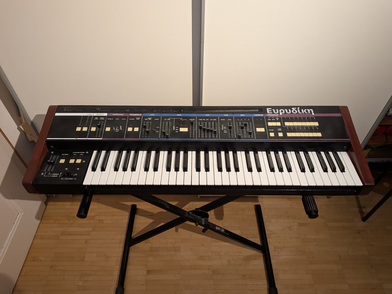
Background
The Roland Juno was a series of synthesizers released by Roland since the 1980s. Compared to its big brother, the Roland Jupiter series, the Juno was a more affordable model, by reducing the number of features. However, the precise layout and slider ranges make the Juno "hard to sound bad" while other synthesizers can get quite hard to control.
Compared to other analog polysynths, the early Junos are minimalistic with only six voices, a single oscillator and a single envelope for both filter and amplifier. All of that does not matter in regard to the praised chorus section, producing a warm and smooth widening effect. The Juno also featured a pattern storage, letting a user store certain slider positions for later recall.
Analog polysynths are expensive and complicated to build since they essentially feature multiple copies of monophonic analog synthesizers on multiple boards. Furthermore, the panel settings can not be controlled using simple potentiometers, but rather must be set by digitally controlled switches, digitally controlled resistors or digital to analog converters. All of those are controlled by a master board with a microcontroller.
Design
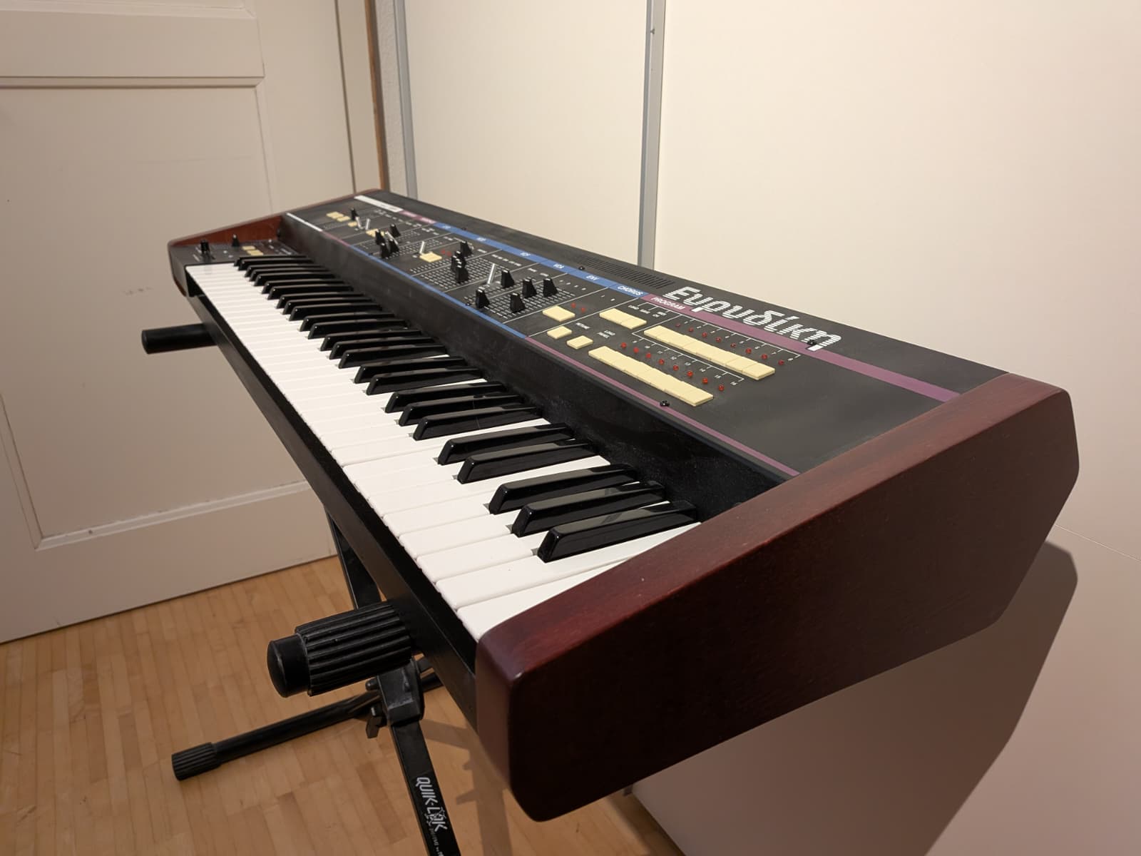
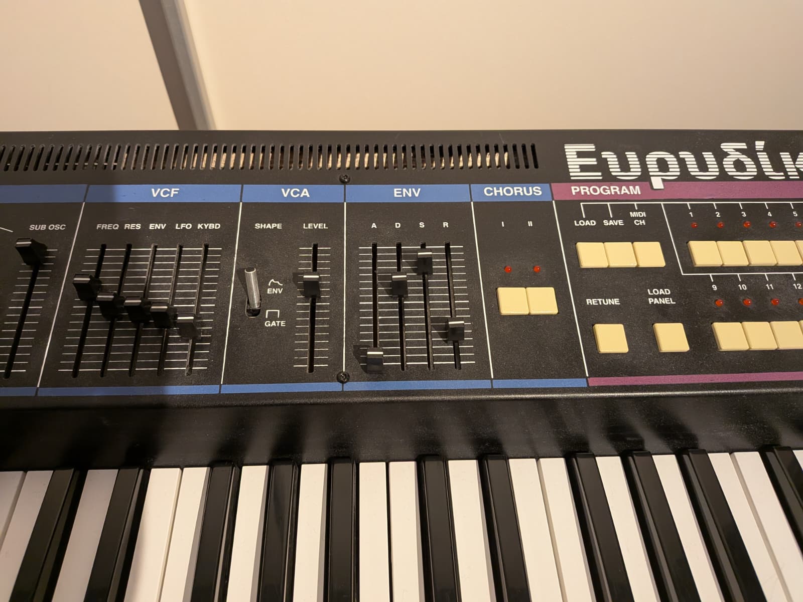
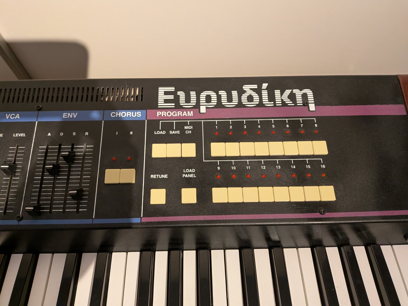
For the simplicity and the beloved sound, I chose to imitate the Juno's design as I did with the Minimoog clone in the past. However, I added my own twist. The synthesizer is named after Ευρυδίκη (Evridiki or Eurydice) from the Greek mythological tale of her and her husband Orpheus, in which Orpheus descends into Hades to save her using his enchanting music.
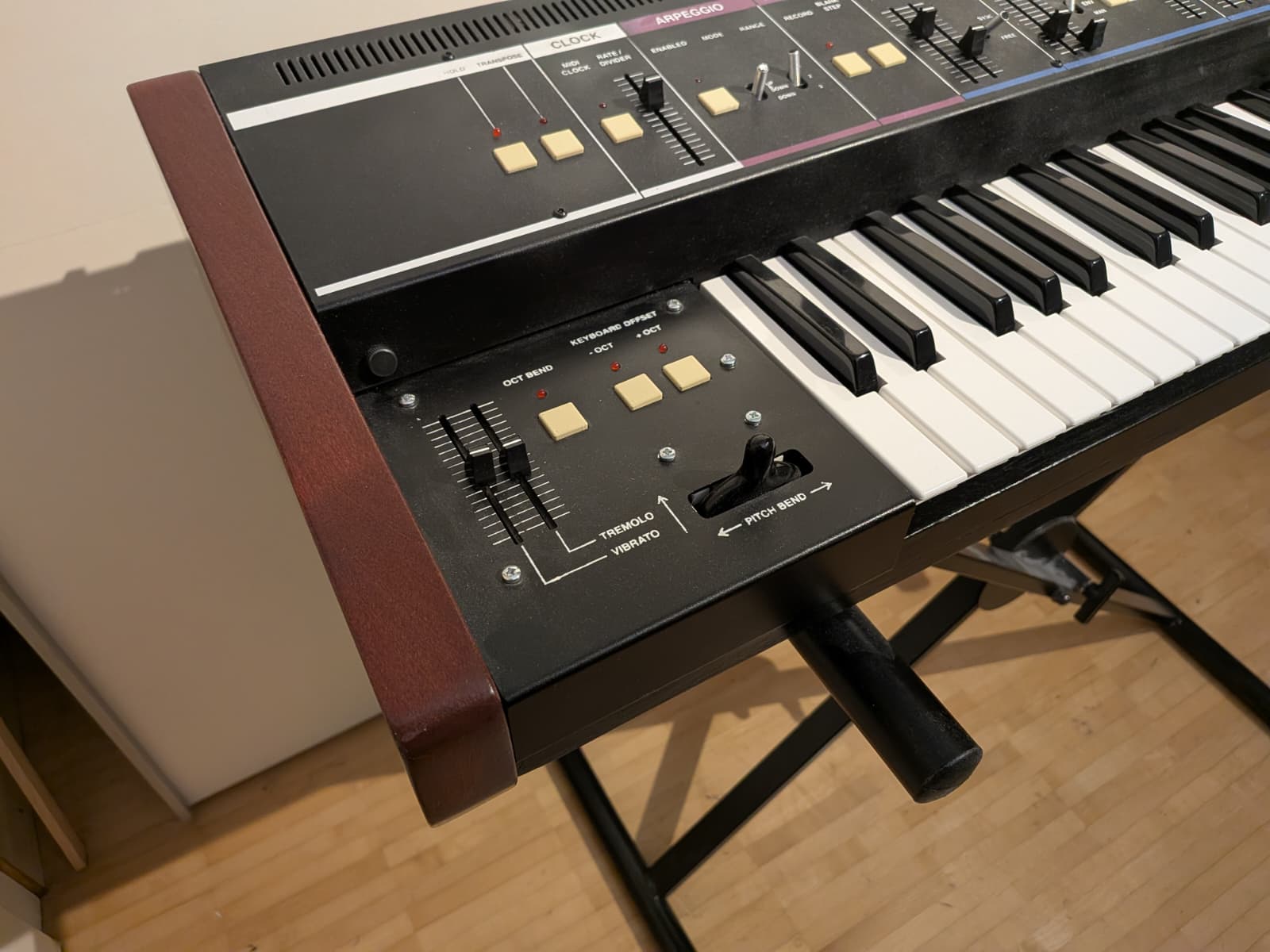
The number of voices was rounded up to a practical eight instead of six. Also, I added a sequencer section in addition to the arpeggiator, which has worked out pretty well.
The synthesizer was modeled in Solidworks and the electronics were designed in KiCad. The entire design was built around an old salvaged keybed from an old MIDI keyboard of my friend (shoutout to Jylorant).
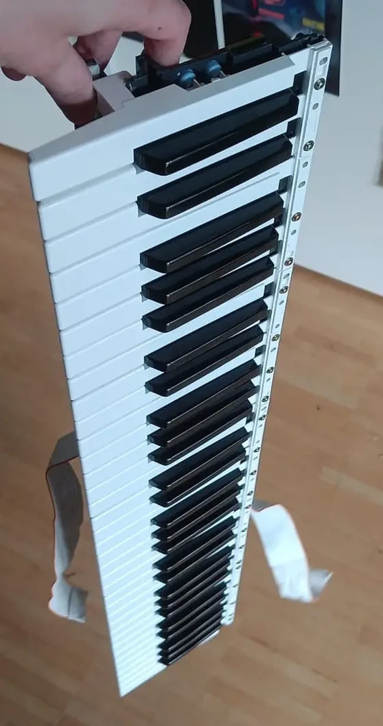
The chassis is built from wood with solid endpieces and the two panels are mounted on top. The four voice boards with the mainboard are at the heart of the synth. The top PCB screws into the top panel directly.
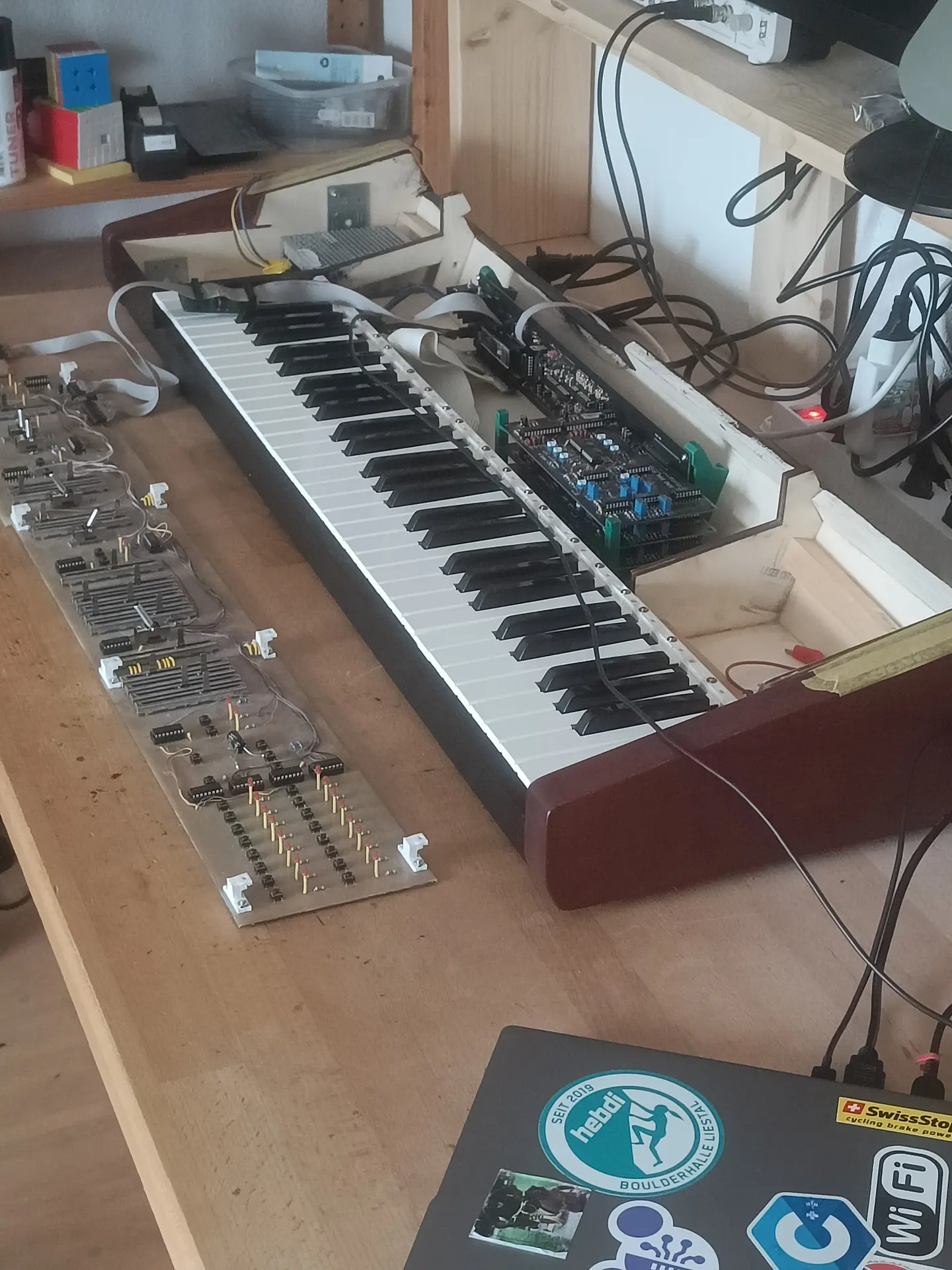
Electronics
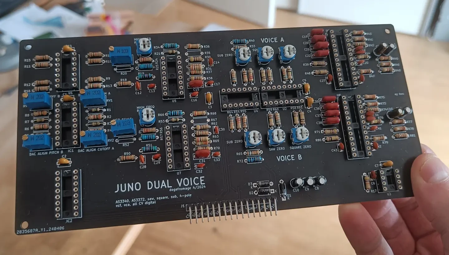
The electronics are of course the key part of this project, since building an analog synthesizer involves creating all the circuitry of the main sound generation with analog components, instead of simulating it digitally as it is done in virtual instruments on the computer. Therefore, I created four voice board copies, each featuring two voices on it. This connects to a main board using headers. Another massive board is needed underneath all of the front panel more as a structural support for the faders and switches on the front panel.
The professionally made circuits were designed in KiCad and ordered via JLCPCB. The front panel circuits were not. More on this later...
Voice Board
Here, I spent a lot of time designing the voice board first on paper. Choosing the right components drastically simplifies the design. A big simplification step was using compact ICs designed for use in analog synthesizers. Also, all of the modulation like envelopes, LFOs and their mixing is done digitally. The main audio signal however is still created analog. This was done similarly in the Juno, which used even more drastic measures with their digitally timed oscillator chips. Offloading the modulation to the code also allows tuning the modulation a lot for ease of use and adjusting the ranges of values. This sounds very boring in text but it really makes a difference when using the thing.
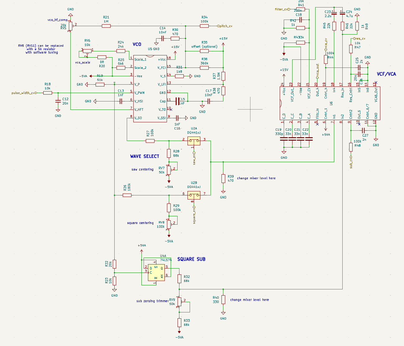
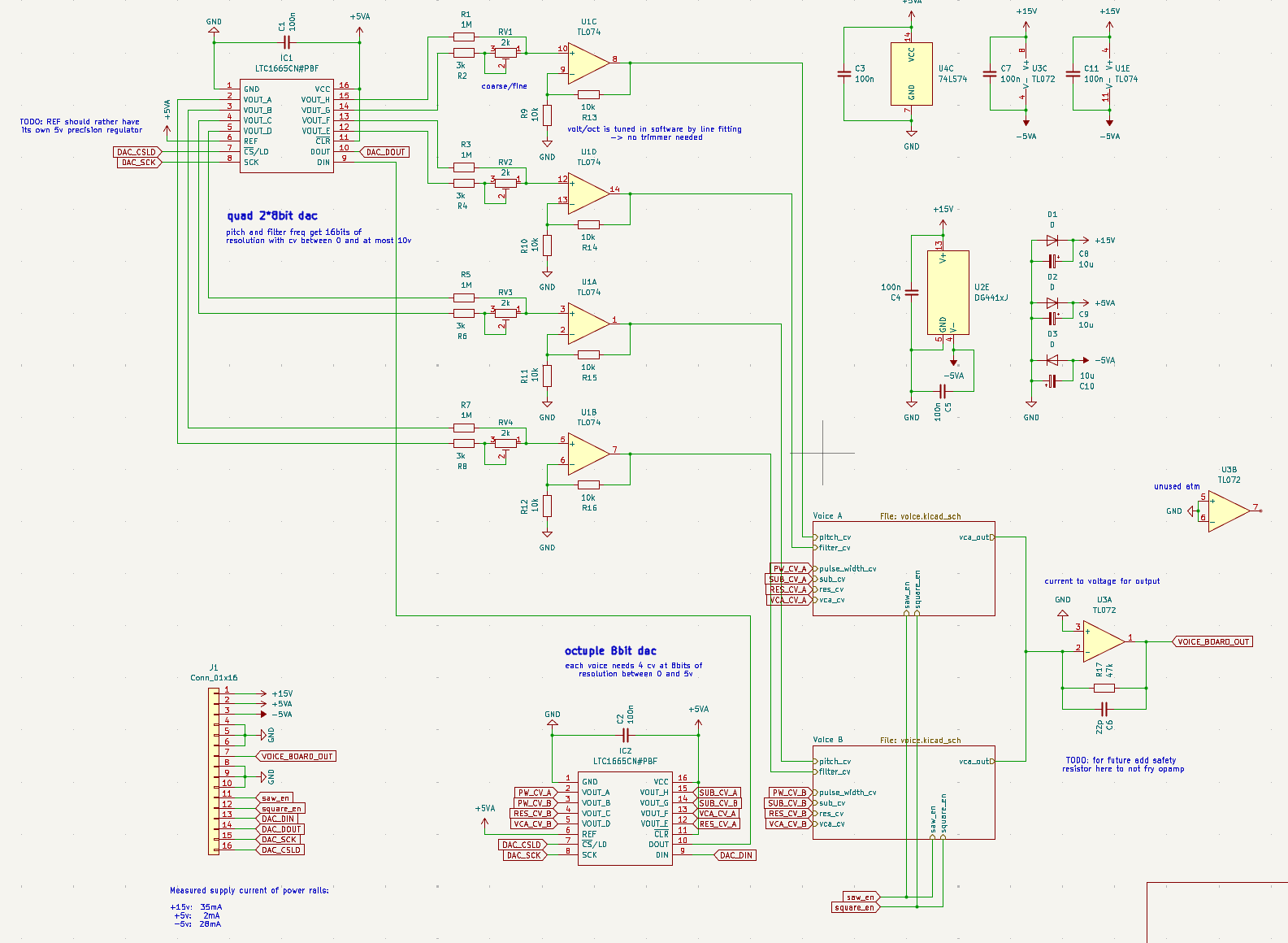
For a background in subtractive synthesis with analog circuits, my Matura paper and the page on my Minimoog clone is a good summary. Similarly to there, I chose the AS3340 as my VCO chip. A chip that drastically simplifies the analog voice is the AS3372. It is perfect for my purpose, since it can be configured as a dual input mixer followed by a four-pole resonant VCF and finally a VCA. Combined with the AS3340 VCO this gives us a whole voice using only two DIP-16 chips.
For the extra features of the Juno-style voice section, we need a suboscillator, which can be constructed using a D-Flip-Flop that halves the square wave to be an octave lower. The DG441 digital switch lets us toggle the square and saw waveforms to enable none, one each or both at once.
The interesting part of this voice card is rather the source of control voltages. While other vintage synths use a single DAC followed by multiplexers and sample and hold circuits, I found that way too cumbersome. Therefore, I looked for a cheap DAC, where I settled for the LTC1665 with eight separate eight-bit outputs. 8 bits is too little for pitch control. Therefore, one of them is used for eight channels of eight-bit control voltages and the second LTC1665 for four channels of sixteen-bit pitch control voltages. The accuracy is improved by summing two channels together with one being 256 times scaled down using an op-amp. The four high-precision outputs are used for pitch and VCF-cutoff on both voices. VCFs with sustaining resonance can be played as a note and thus need precise pitch control as well.
Mainboard
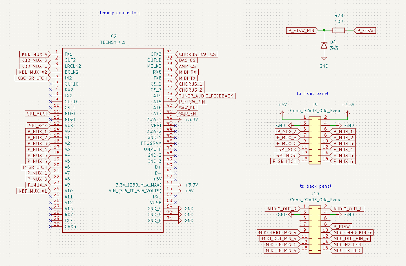
The mainboard centers around a Teensy 4.1 microcontroller. This is basically like an Arduino but more powerful and with tons of IO features.
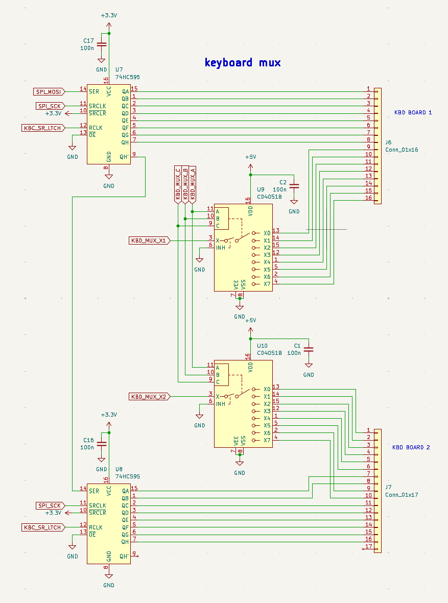
Like most MIDI keyboards which I have used, this one features a button matrix with series connected diodes. Therefore, it can be connected using two 74hc595 shift registers and two 4051 multiplexers.
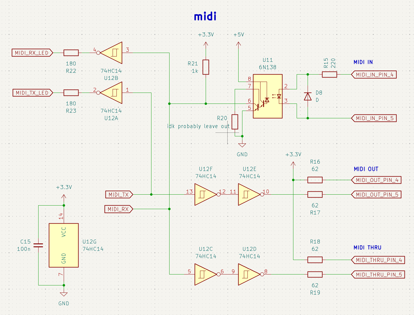
Of course, we also need MIDI. This circuit is quite standard and connects to one of the UARTs on the microcontroller. The optocoupler is required to galvanically isolate other MIDI devices and prevent unsafe ground loops.
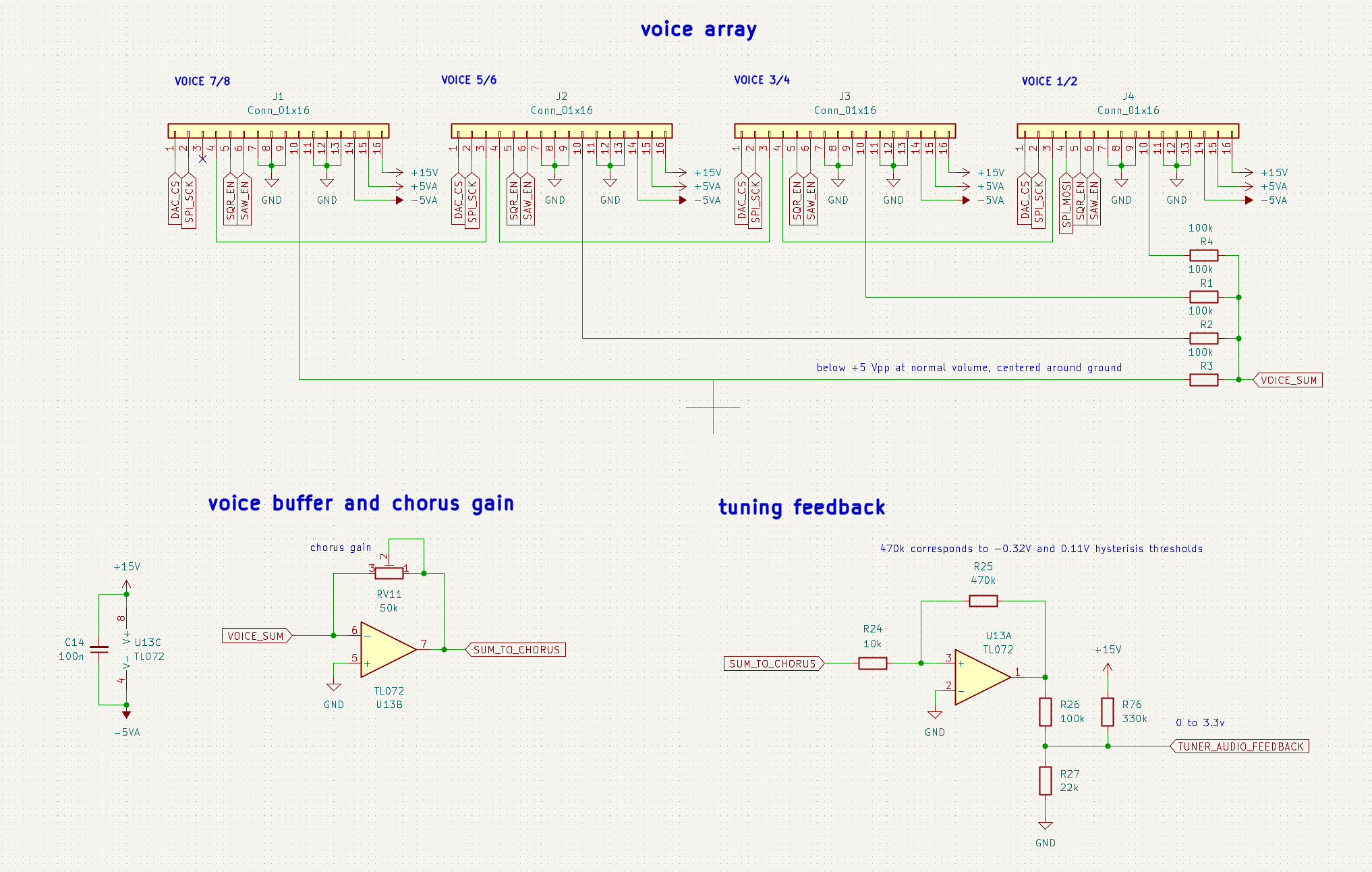
Now, the four voice cards plug into headers at 90-degree angles. The four audio signals get summed up using an op-amp and the other side of the op-amp is used for the tuning feedback circuit. It is configured as a Schmitt trigger, to not double count a rising edge.
For precise tuning, the voice can be configured to output an unmodulated square wave with filter fully opened. The microcontroller then counts the number of rising edges and can thus fit a regressive model to the pitch curve, creating a precise tuning. The same thing can be done for the filters sustained resonance, where all other oscillators are disabled.
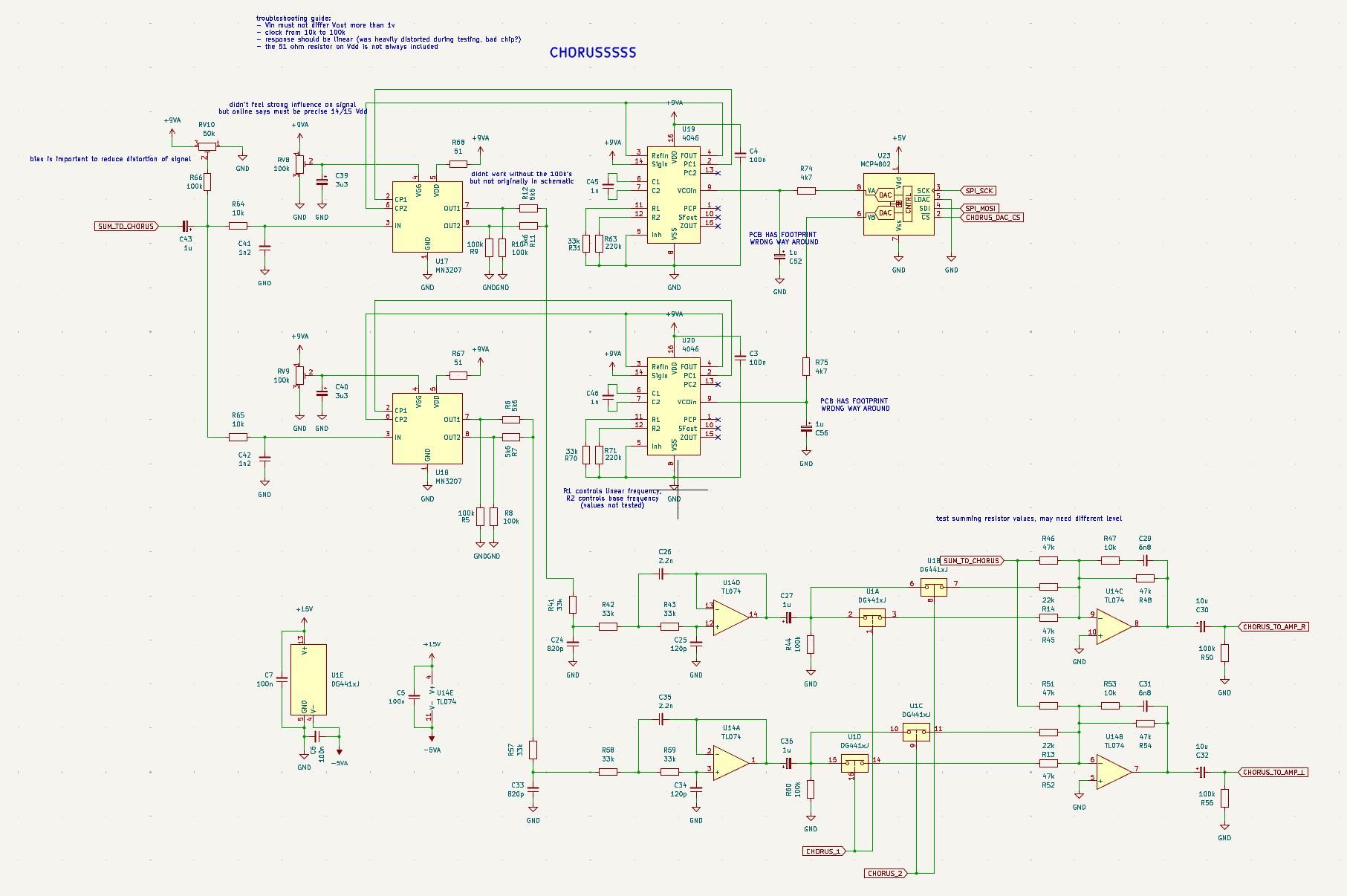
The chorus is the most complicated bit of the mainboard. I myself only understand parts of it and it also never worked 100%. But it does sound like a chorus and that's what matters.
The circuit is a stereo chorus built around two MN3207 1024-stage bucket-brigade devices. Each audio channel thus gets one chorus mixed to the original signal creating a wide stereo effect when enabled. The BBDs are controlled via two 4046 VCO chips. This setup was mixed together from many circuits I found online. I cannot trace it back to a single source.
The later mixing stage was designed by me, where a further DG441 allows the user to select between the four chorus modes using switches like in the original Juno. What the chorus also needs is the delay time shifting slowly with around 1-10 Hertz. This is achieved by an MCP4802 two-channel DAC that controls the frequencies of the 4046 clocks. The three enabled chorus modes on the panel mainly provide different amplitudes of mixed in chorus via the DG441 but also different modulation frequencies, depths and phase offsets between both channels. There is a vast number of possibilities of course, but I mainly chose a few at random giving essentially three options at different intensities of chorus.
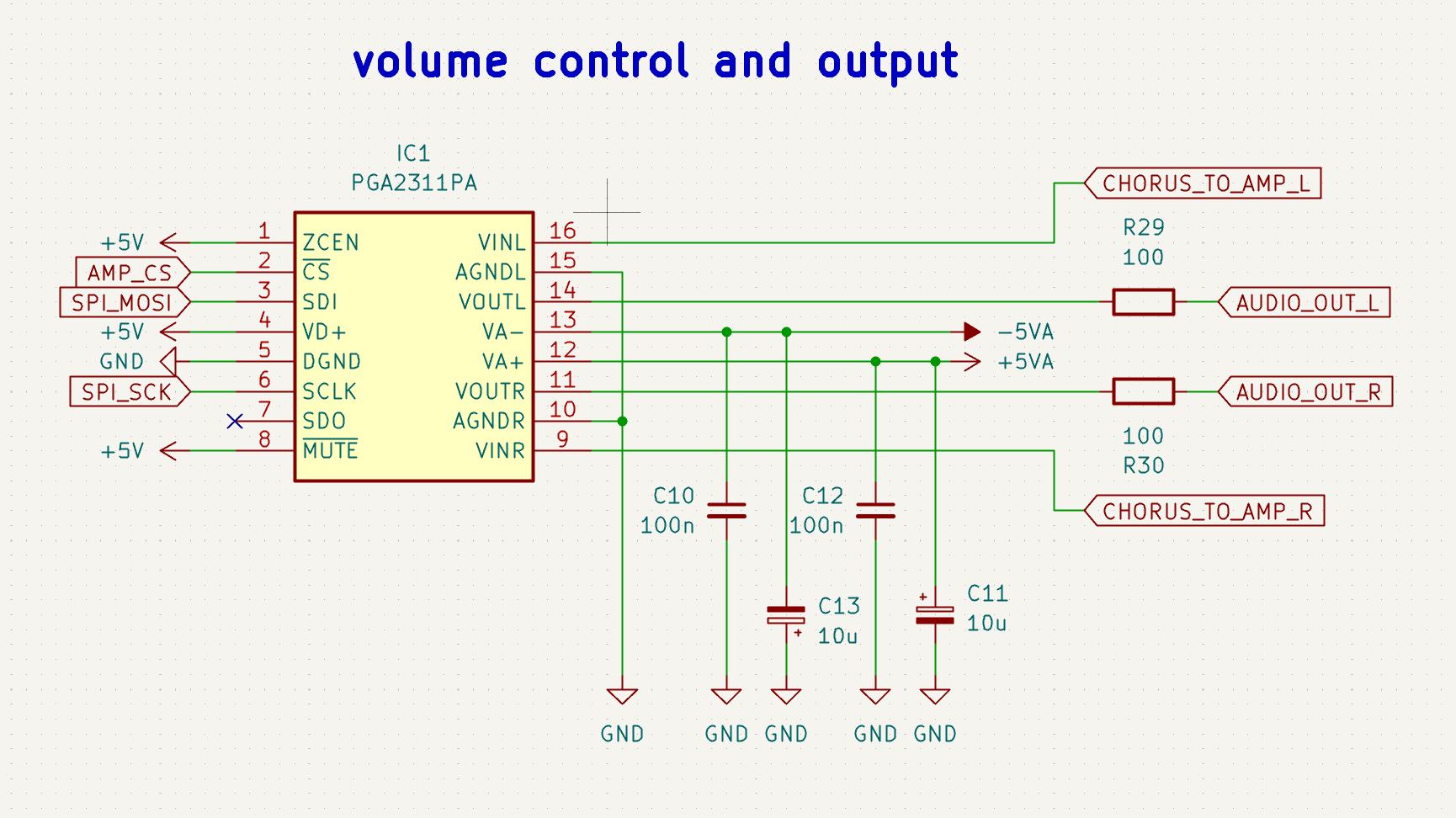
At last, the output section is comprised of a single PGA2311 stereo volume control chip. This IC is rather expensive but I still chose it for the following reasons:
- I want to create a stereo output signal with the ideal line out impedance, which I did not want to endlessly research.
- The output of my synthesizer should not break some other expensive audio equipment it is plugged into.
- The chip should offer a very large exponential range of output volumes without distorting or clipping.
For that, the IC is ideal and it does exactly that.
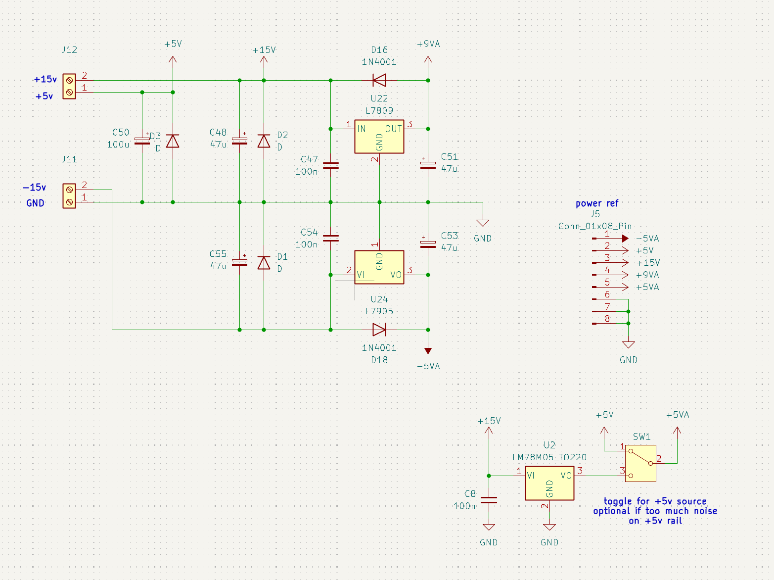
Power can not be neglected and high quality audio devices require a very steady power line to mitigate noise. Also, to minimally deal with wall power voltages, I used a premade internal power supply unit that converts wall power to three rails: -15V, +5V and +15V. This is almost perfect since the synth chips usually take -5V and +15V while the digital electronics can use the +5V rail. The -5V rail however had to be regulated down using a 7905 LDO. Some analog parts also needed +5V and thus I created a second +5V rail with another LDO to minimize digital and analog crosstalk, especially since many LEDs are turned on and off which will likely lead to audible noise in the output. The chorus BBD chips require +9V. Thus another LDO was needed. Since analog audio currents stay very low, the LDOs are fine and do not overheat. Still I added small heatsinks.
Panel Electronics
The main panel mainly serves as a structural component, holding the sliders, switches and LEDs in place and resisting the pushing force on the panel. In consumer electronics, this is usually a cheap single or double sided large PCB that mounts to the bottom of the panel.
Creating the panel myself was quite intense. It started out with me realizing that ordering an 800mm wide panel was not that realistic and affordable. So I attempted to etch my own, which I have never tried before. I found a store selling around 30cm large plates of single sided FR4 PCBs. Three of those tied together could solve my problem.
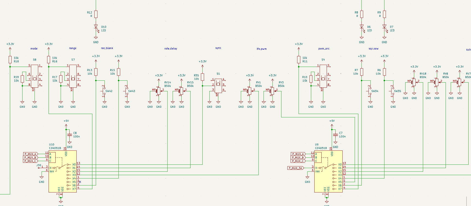
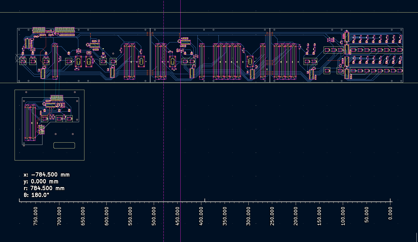
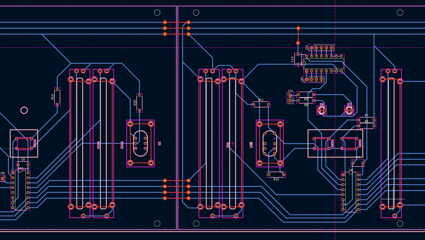
Another issue was getting the print on. To not have to deal with transfers or photo-resist films, I just chose to paint it on. The traces can be quite rough since I have tons of space. So I tested multiple pens to see which has the best etch-resistance (STAEDTLER Lumocolor was best, but I think buying one designed for the job would have been even better).
So I hand-punched little marks into the copper with the help of A4 paper prints of the pcb design that I could use as a stencil. Then I painted on all the traces. This was fun!
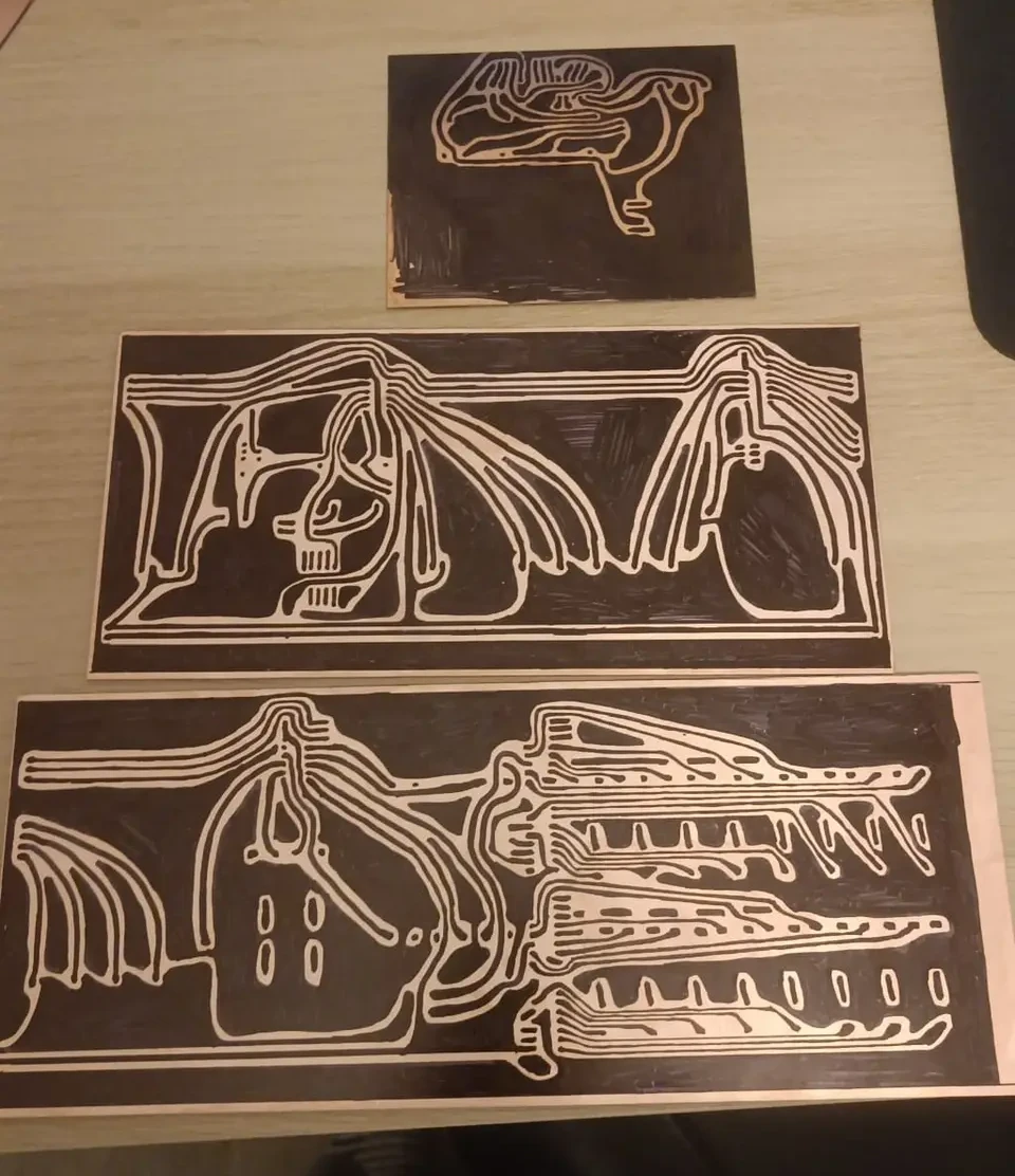
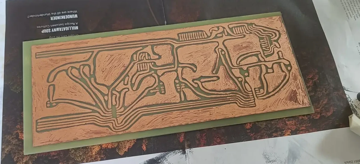
The holes I later drilled with a small drill press and tiny bits I ordered online. I got very close to breaking the last bit but thankfully I did not.
Firmware
The firmware for the Teensy 4.1 carries a lot of the complexity of the project. Still, it is mostly boring low level code. The firmware does however have to do all the following things at once without blocking or delaying:
- Program all 8 DACs with each 8 channels at a rate of around 500 Hertz, where fast modulation is possible and latency is negligible
- Receive and send MIDI notes and precise clock signals
- Read the panel and control the LEDs
- Load and save patches
- Do tuning
- Simulate the virtual modulation sources
- Manage the complex behaviour and state of the arpeggiator or sequencer without blocking the execution
What helped a lot when designing the code was to encapsulate behaviour into object-oriented classes with meaningful purposes. This diagram shows the overall relationships between the classes:
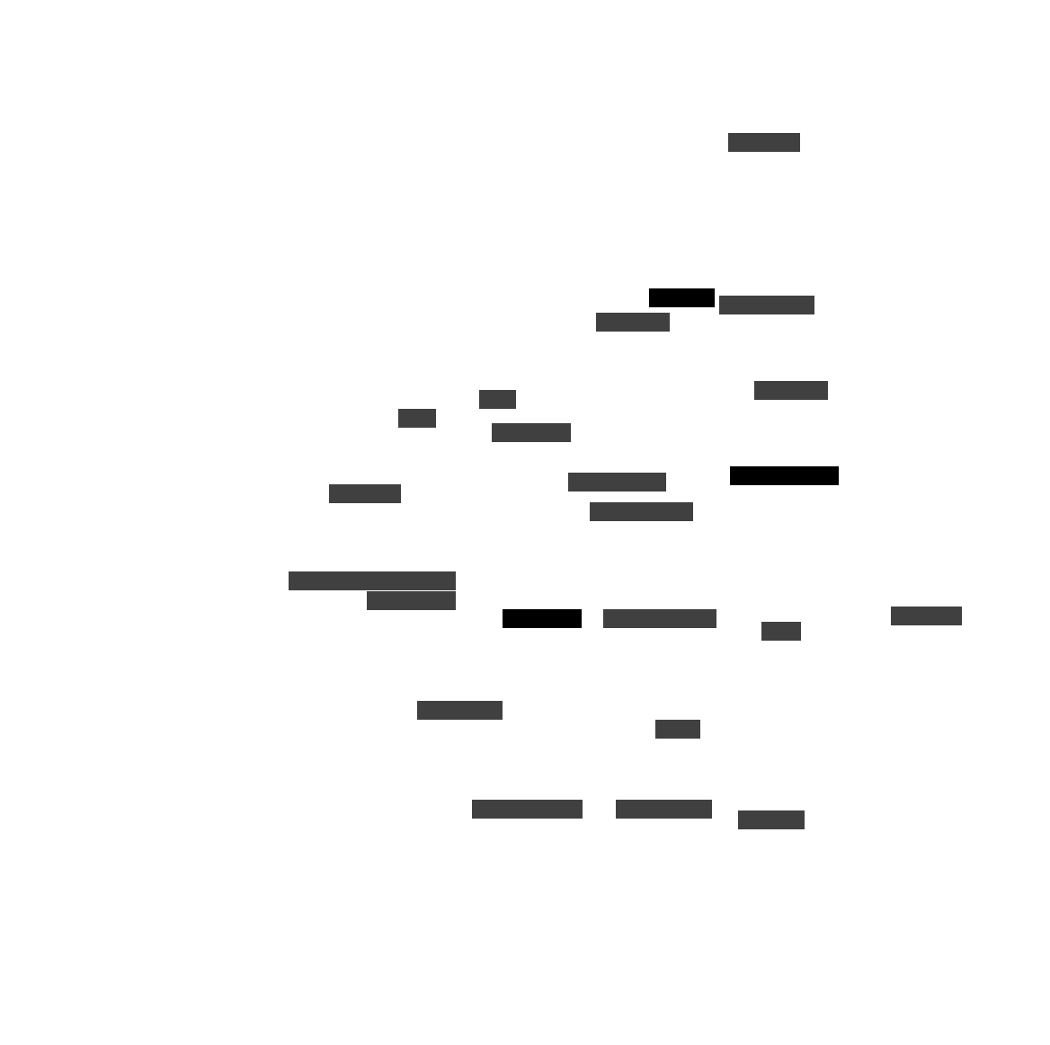
You can explore or use the code on GitHub. I want to list a few interesting sections here without boring you:
tuning.cpp starts tuning the oscillators one by one upon request on the front panel. This is the only routine that is blocking, i.e. stops everything else the synth is doing. The tuning works by attaching an interrupt to the tuning input pin that counts each edge in a given precisely timed window. After measuring a range of inputted vs measured frequencies, an order two polynomial i.e. a parabola is fitted to the values and stored in a tuning profile that gets loaded every start of the synth. Therefore, the synth only has to tune sometimes, mostly it stays in tune.
In instrument.cpp most of the fun stuff is happening, such as Voice::update(...) and Instrument::update(...) which both contain the main logic that feeds the panel values into the digitally simulated LFO and envelope and then calculates the final six DAC voltages pitch, cutoff, resonance, pulse_width, sub and volume.
player.cpp is definitely my least favorite file to have worked on. It contains the layer in between the keyboard sending a key and the synthesizer reading it and thus handles the arpeggiator's and sequencer's behaviour. It is very prone to bugs and edge cases that sometimes I have only noticed way later.
panel.cpp is nice since it reads the panel's faders and looks funny in code. With some clever macros, I was able to simplify the fader logic quite well. Panel::update() contains the heart of the panel's logic and how the faders actually behave to the user, which can be underestimated quite easily.
Chassis
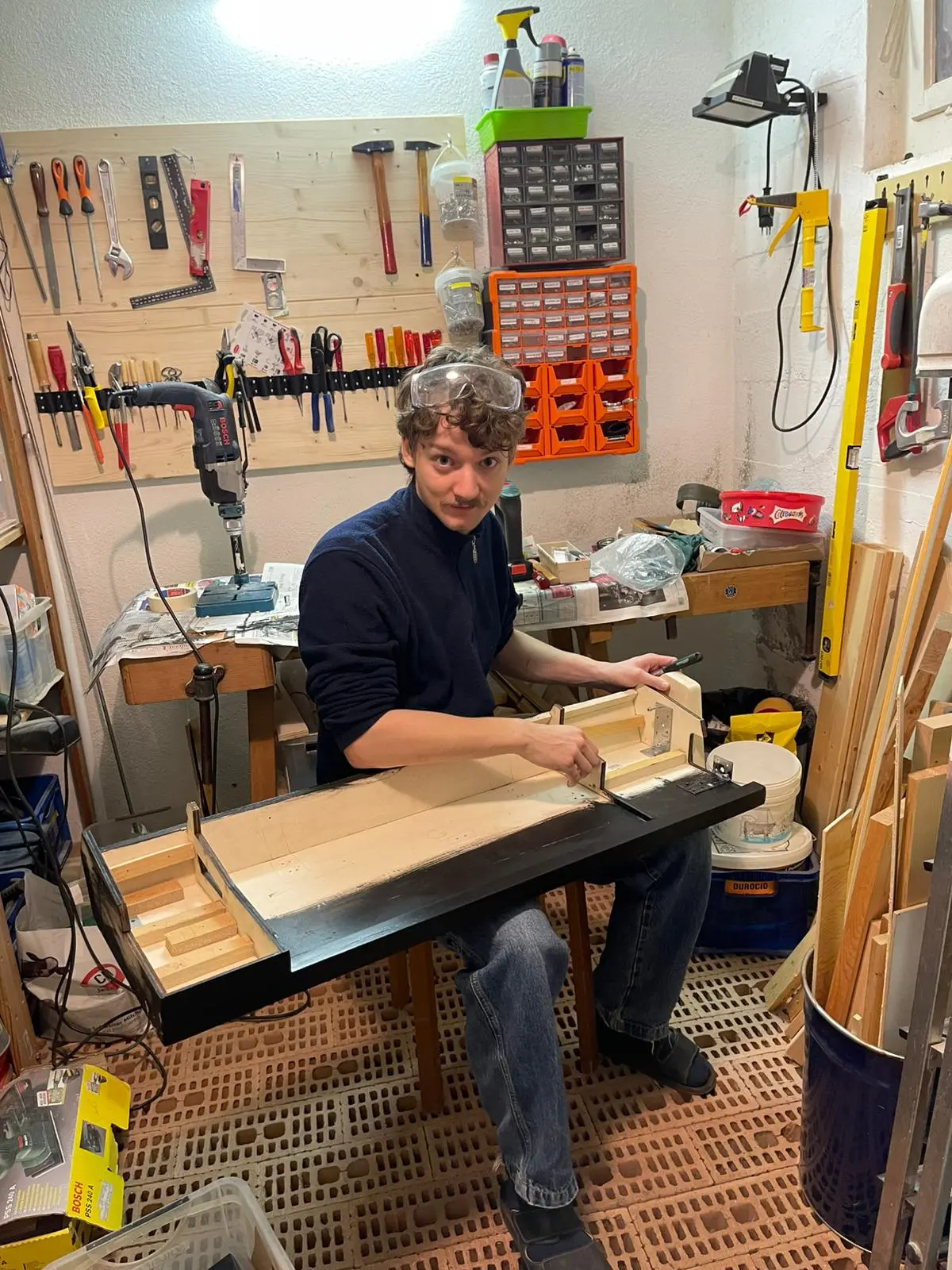
This part was the most fun, as with many wood projects. On the laser cutter in my university's makerspace, I cut out small fins and endpiece mounts. Those give the chassis high strength and cut the weight down drastically compared to earlier projects of mine. The large pieces are plywood and the two endblocks are some hard wood I found in a scrap bin. I screwed them in from the inside using large M6 inserts for high stability and an untouched outside.
The shell is painted black and the end pieces are stained with Mahogany woodstain (Beize in German). Then I added multiple layers of clearcoat with interlaced sanding.
Panels
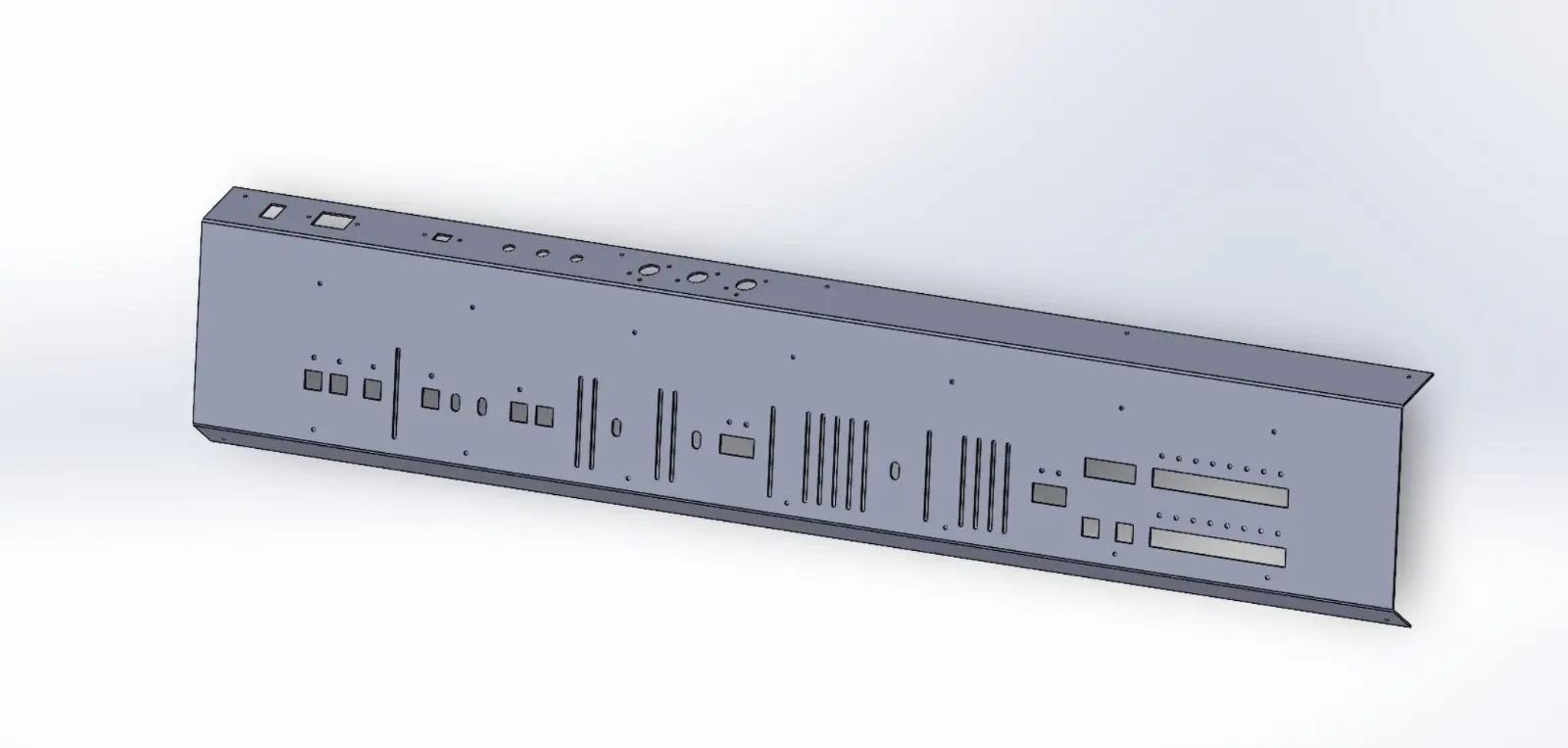
The panels puzzled me for a while. I could not produce panels like the ones from the Juno myself. In previous synths, I only had to cut them along the outside and drill holes. But now, I have to create many slots into the panel and do precise bends along the edges. I attempted to use a CNC at my secondary school, which I spent a lot of time setting up because no one knew how to, until I broke a few bits and eventually gave up. Finally, I contacted my local metal worker business and asked them for an offer, which came to below 200 CHF, which surprised me as I thought it would be much more...
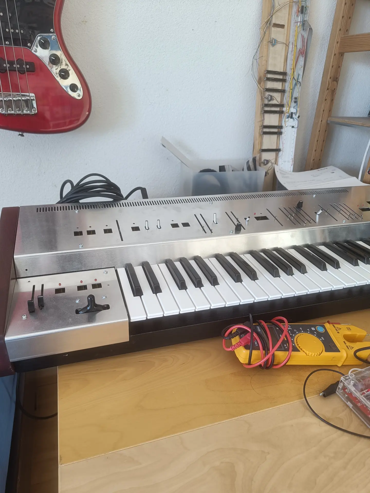
The paint job was unfortunately a dark story. Compared to my last synthesizer paint job, which went surprisingly well, this one got rather complicated. The order of applying the paint matters a lot, this is what I eventually found out:
- Painting on aluminium requires a special aluminium primer first
- The black base coat follows on top
- The colored lines must be screen printed to make them sharp in multiple colors with multiple screens
- The white text must be painted with screen printing with multiple screens
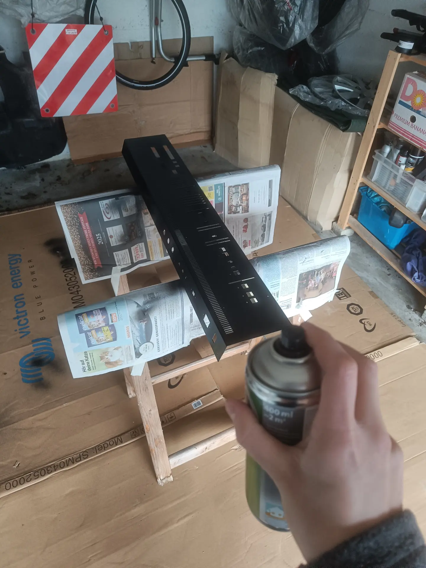
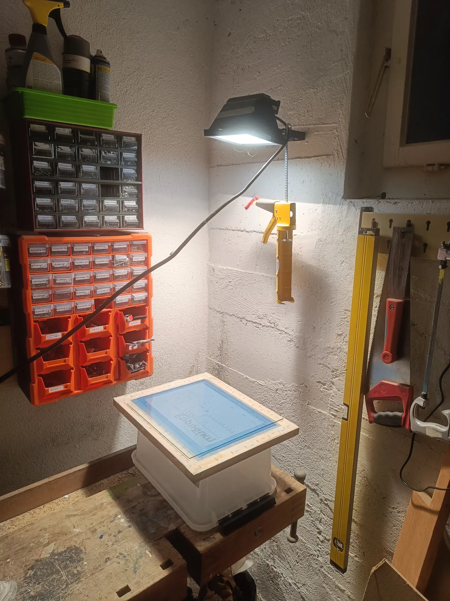
That was the theoretical plan. However, the following problems occurred one after the other driving me insane and always having to repeat everything...
- While screen printing, a small error will ruin the current print, so everything not dry must be washed away. If this is done with a solvent, the layer underneath is going to dissolve and be ruined
- Multiple screens must be used since the panel is large. The order matters, since the overlapping paint must be dry such that it does not smear while printing the next one
- The staples in my DIY screen scratch big holes into the base layer paint
- Paint with the same solvent as the base layer will dissolve and mix with the base layer
- The clear coat I used actually dissolves the base layer as well and when I thought I was done, the whole panel got a weird spiky texture :(
All of these problems made this project go on for a year longer, while everything else already worked quite well... However, I finally managed to somehow end it, even though the final panel finish is a bit weird. With a polishing cloth, I was able to softly sand off the small bumps left from the improperly applied clear coat.
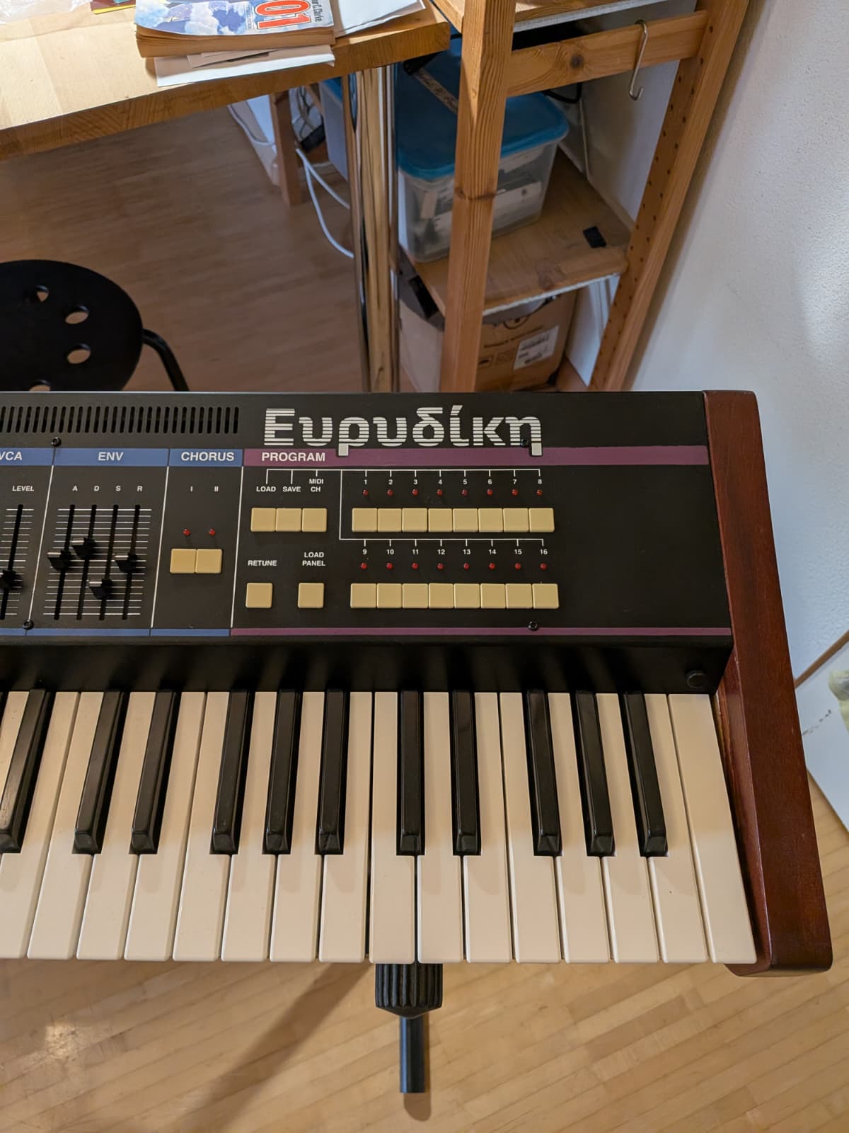
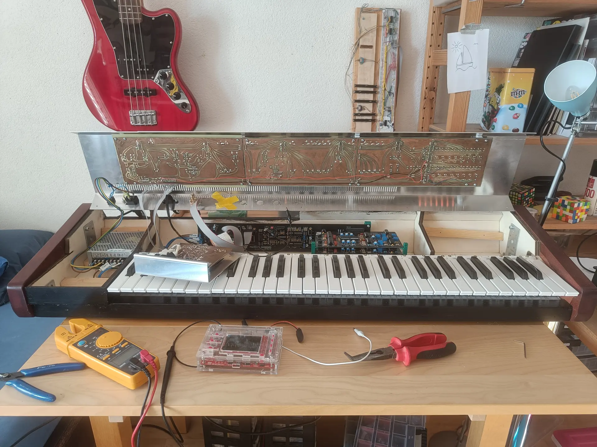
Final Result
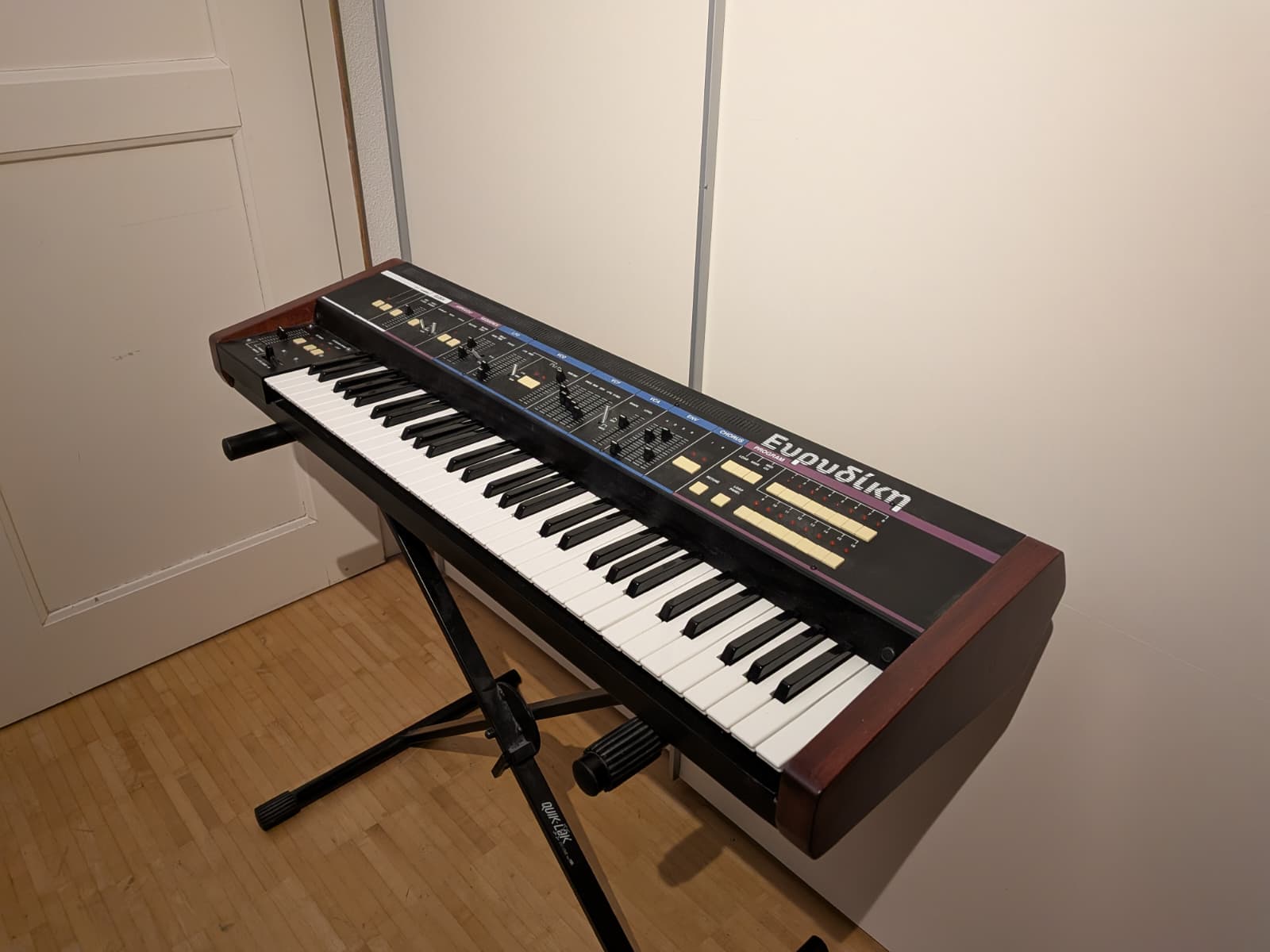
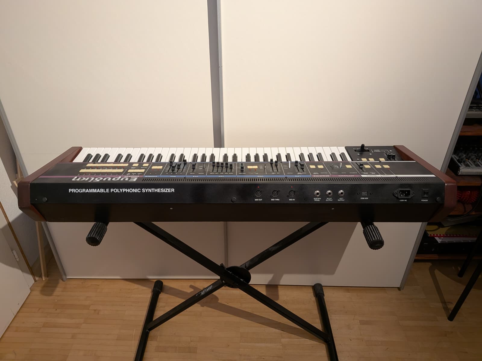
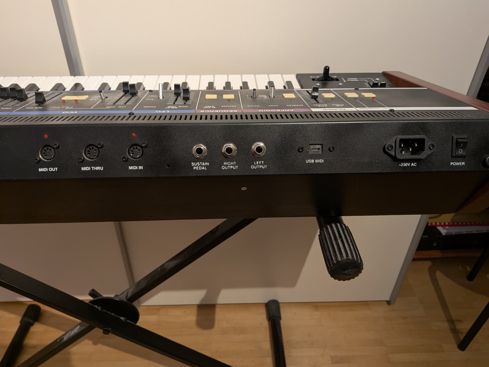
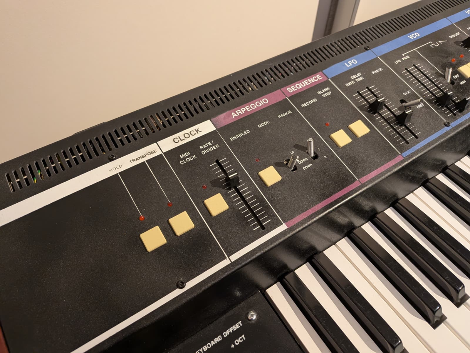
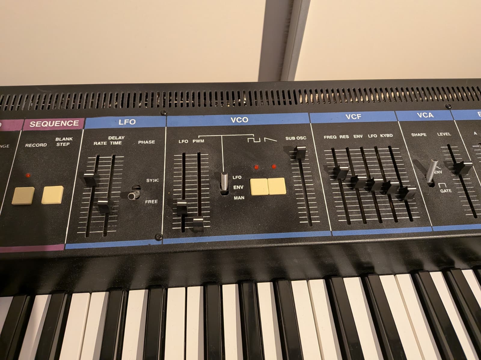
The control section contains in addition to the standard arpeggiator from the Juno also a sequencer, which I designed. With "Record" held down, the number of steps can be selected with the number panel. Then the sequence can be recorded and blank steps can be entered.
Demos
The demos might contain bad playing and poor camera quality. Don't be disturbed!
I must post more demos in the future showing the niche sounds that can be achieved! TODO...
Files
Feel free to ask me a question about the process or ask me if you want any files, code, cad or schematics :)