[2026] STM32-based 16-channel Analog Servo Driver with Force Feedback and 16 Potentiometer ADC Inputs
For my animatronic hand project, I required specific features without spending too much on complicated driver boards. Therefore, I made my own complicated driver board.
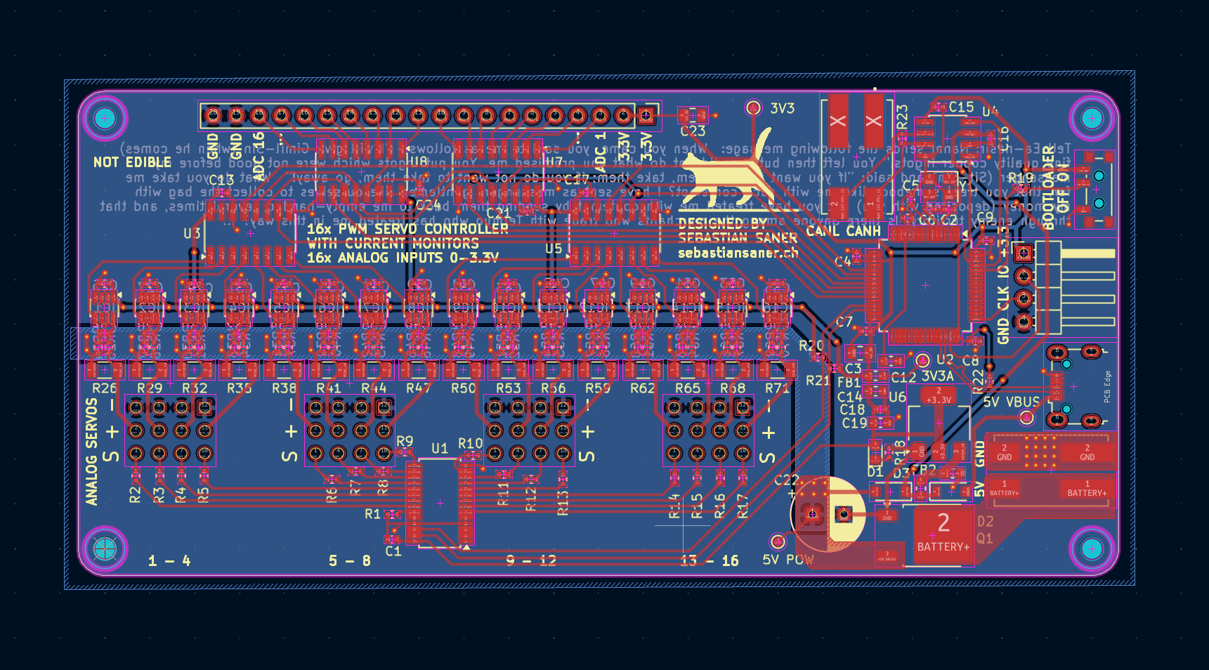
My board is tailored to the hand project, but the goal was to use it for many future animatronic projects. It thus features:
- 16 servo channels run via a PCA9685 PWM driver that is sending PWM signals to the analog servos.
- 32 ADC inputs (16 of which are for current sensing)
- 16 INA190 current shunt amplifiers for current sensing
- STM32F4 microcontroller
- Micro-USB port
- 10-15 Amps total current on the driver (this is an estimate, will find out someday)
- CAN bus (never tested but board has it)
Servos
Simple RC analog servos are super cheap and come in various sizes. Some are angle-based and others feature continuous rotation, where the input signal controls the speed. All function with a timed signal, which can be controlled using the right PWM driver. A common driver on dev boards is the PCA9685, which can be set up to drive 16 channels simultaneously with a PWM signal.
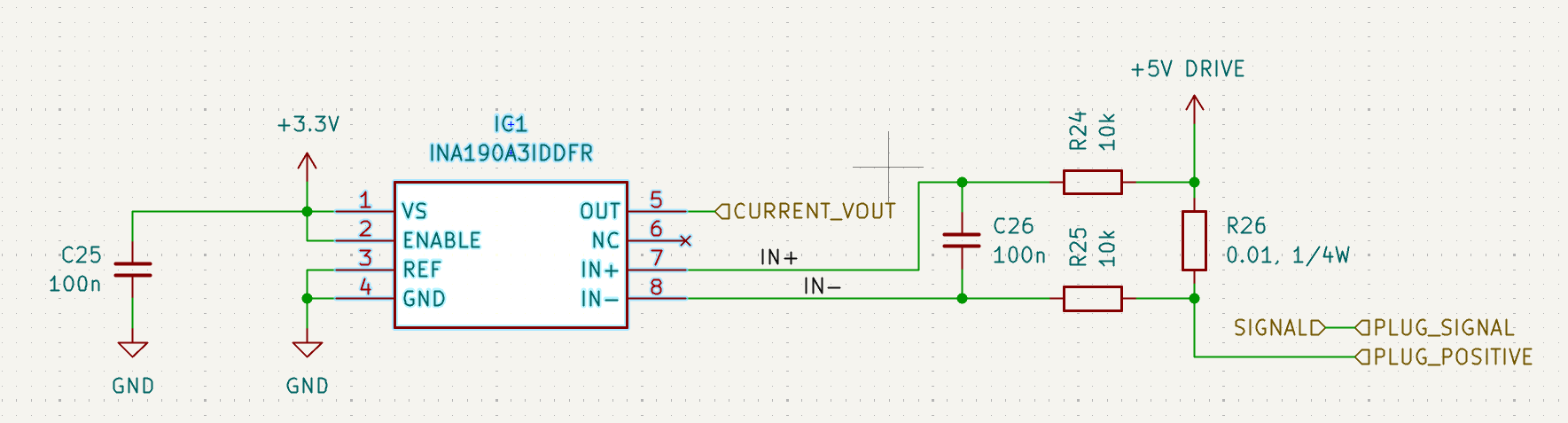
Each servo is connected in series with a shunt resistor (R26). The voltage drop over this resistor is measured by the INA190, filtered and amplified. The INA190 then outputs a clean signal which can be read with an ADC into the STM32. In total, this circuit is replicated 16 times.
Board
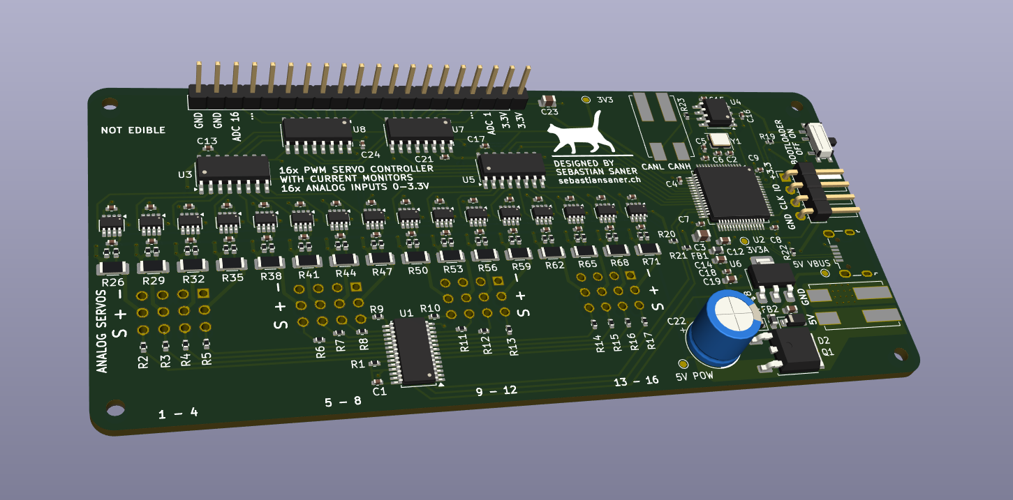
For animatronics, I tried to keep the board extremely compact. All headers can be 90-degree headers, which point the plugged-in wires sideways creating a shallower compact setup. The big cap can be pushed to the side as well.
Building the Board
This is my first SMD project, my first STM32 project and my first project without a dev board. So it was a learning curve...
The two pictures below especially show my gross underestimation of the SMD component size.
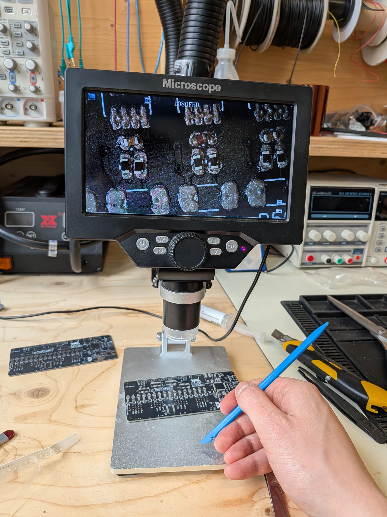
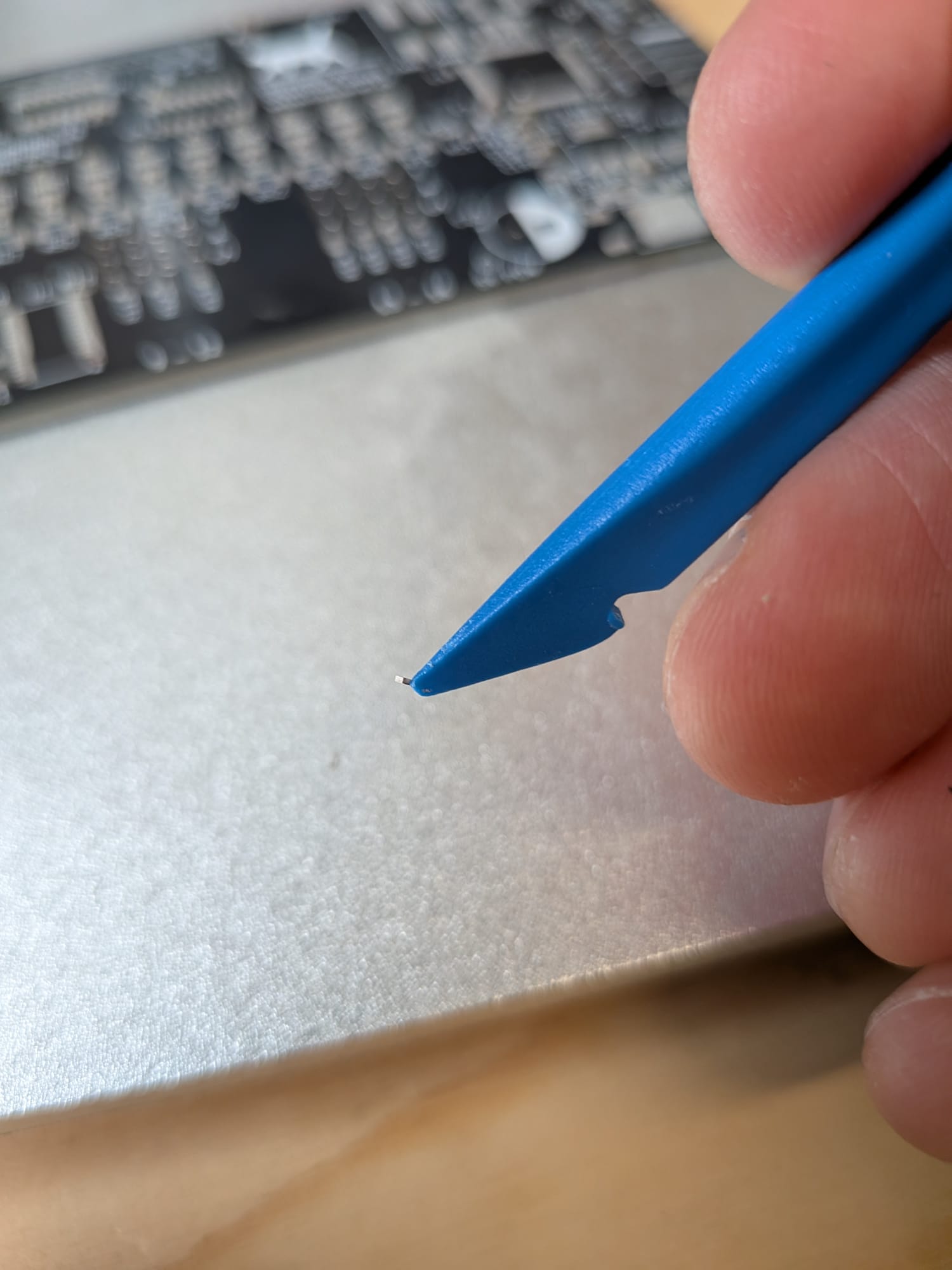
The PCBs and parts were ordered from JLCPCB and LCSC. Since assembly is charged per type of component, I was a cheapskate and decided to build it myself. This led to a horrible half a year of questioning myself why the board did not come to life. I replaced the STM32 with another one, resoldered it aaaand it worked!!! Therefore, I probably fried the first one.
Arm-ing the Board
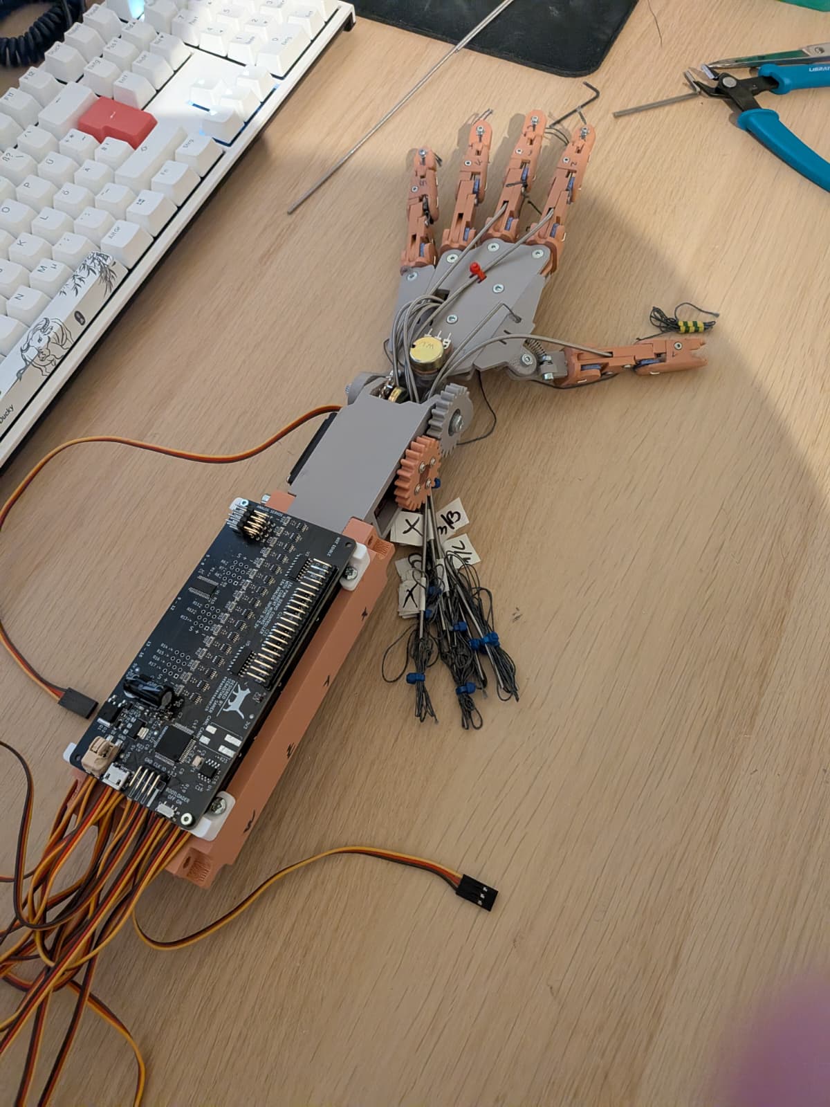
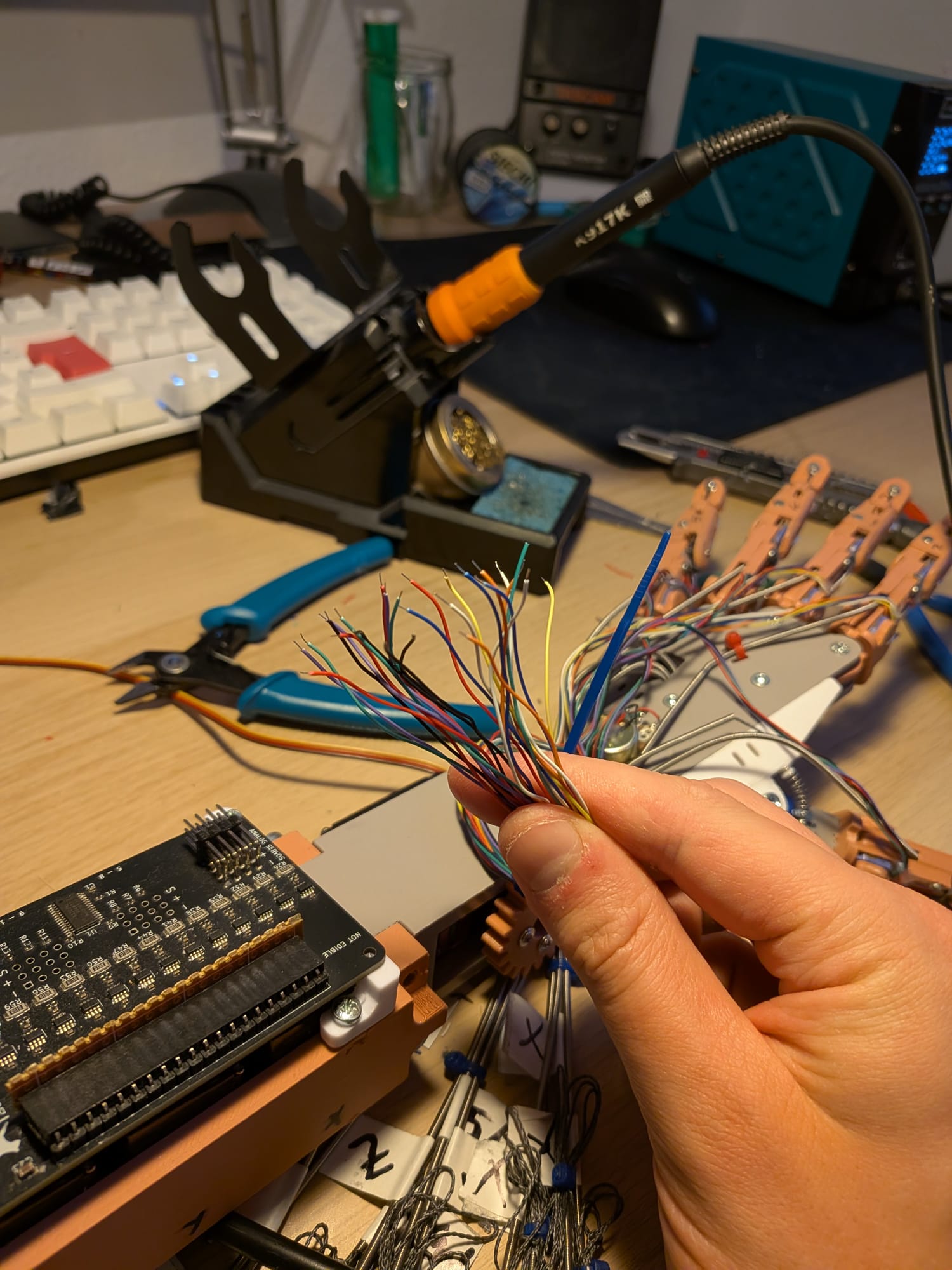
The other pictures show the board in place and the resulting wire mess. Thankfully, I have these very small gauge wires that have a minimal footprint.
Want the files?
If you want CAD files, KiCad schematics or code, feel free to send me an email!